
Pilot-Operated Hydraulic Control Valves: Precision at Scale
How can water distribution networks control large flows and maintain stable pressure without relying on complex external power systems? Pilot-operated hydraulic control valves provide an effective solution by using a small pilot valve to regulate the operation of a much larger main valve. Through hydraulic pressure sensing, feedback control, and automatic adjustment, these valves help improve pressure stability, flow management, pipeline protection, and operational reliability across water supply, drainage, fire protection, HVAC, and industrial piping systems.
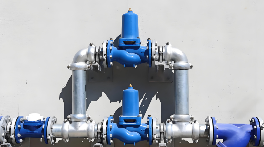
What Is a Pilot-Operated Hydraulic Control Valve?
A pilot-operated hydraulic control valve is an automatic valve that uses a small pilot control unit to regulate the opening, closing, or throttling position of a larger main valve. Rather than requiring a motor or an external electrical actuator to generate the operating force, the system uses the pressure energy of the flowing medium to drive the main valve and maintain the desired hydraulic conditions.
This operating principle is commonly described as “small-scale control of large-scale flow.” A relatively small pilot valve senses changes in pipeline pressure, flow rate, or liquid level and adjusts the hydraulic pressure in the main valve’s control chamber. The resulting pressure difference moves the main valve diaphragm or piston, allowing the valve to regulate a much larger volume of water.
Pilot-operated hydraulic control valves are widely used in municipal water distribution, water treatment plants, building water supply systems, fire protection networks, irrigation systems, HVAC installations, and industrial process pipelines. Their ability to combine automatic operation, accurate pressure regulation, and relatively simple mechanical construction makes them important components in modern fluid control systems.
Why Are Pilot-Operated Control Valves Important?
In a conventional pipeline, a manual valve or basic automatic valve may be sufficient to isolate a section or regulate flow under relatively stable operating conditions. However, large water distribution networks experience continuous changes in demand, upstream supply pressure, pump operating conditions, and downstream resistance.
These variations can create several operational challenges:
- Excessive downstream pressure: High supply pressure can damage pipes, joints, meters, and terminal equipment.
- Insufficient upstream pressure: Excessive water withdrawal from a distribution branch can reduce the pressure available to other users.
- Unstable flow rates: Fluctuating demand can cause inconsistent water delivery and affect process performance.
- Water hammer: Sudden changes in flow velocity can generate pressure waves that threaten pipelines, pumps, and valves.
- High maintenance requirements: Conventional control arrangements may require frequent manual adjustment or more complicated actuator systems.
Pilot-operated hydraulic control valves address these challenges by automatically responding to changes in hydraulic conditions. Different pilot configurations allow one main valve platform to perform pressure reduction, pressure sustaining, pressure relief, flow limitation, level control, and other functions.
The American Water Works Association recognizes these valves as a distinct category of waterworks equipment through ANSI/AWWA C530-22, which establishes requirements for pilot-operated control valves, including design, sizing, verification, testing, delivery, handling, and storage.
Main Components and Structural Design
A pilot-operated hydraulic control valve is not simply a conventional valve with a small regulator attached. It is an integrated hydraulic control assembly in which the main valve, pilot control, connecting tubing, and auxiliary components work together to achieve automatic regulation.
Although the exact configuration varies according to the required function, most systems contain three fundamental components: the main valve, the pilot valve, and the hydraulic control piping.
1. Main Valve: Controlling Large-Volume Flow
The main valve is the primary flow-control component. It generally consists of a large-diameter valve body, a movable disc or plug, a diaphragm or piston assembly, and a control chamber.
Its principal responsibilities include:
- Allowing or restricting the flow of the working medium.
- Regulating the pressure difference between upstream and downstream pipelines.
- Responding to hydraulic signals generated by the pilot valve.
- Maintaining the required flow conditions under changing operating circumstances.
The main valve is commonly available in globe, angle, and Y-pattern body configurations. Each design has different hydraulic characteristics, installation requirements, and space considerations.
| Main valve configuration | Structural characteristics | Typical applications |
|---|---|---|
| Globe type | Compact control arrangement with a relatively direct flow path through the body | Water distribution and pressure regulation |
| Angle type | Inlet and outlet are arranged at approximately 90 degrees | Pipeline layouts requiring directional changes |
| Y-pattern type | Inclined flow passage designed to accommodate specific installation and flow requirements | Specialized waterworks and industrial systems |
The main valve may use either a diaphragm-operated or piston-operated mechanism.
Diaphragm-operated main valves use a flexible diaphragm to separate the control chamber from the main flow passage. Changes in control chamber pressure move the diaphragm and reposition the valve disc. This arrangement is widely used in water distribution systems because of its relatively simple construction and convenient maintenance.
Piston-operated main valves use a movable piston to control the opening. They are selected for applications where their particular pressure, structural, or operating characteristics are advantageous.
The selection between these designs should consider operating pressure, differential pressure, flow characteristics, required closing performance, and manufacturer specifications.
2. Pilot Valve: The Hydraulic Control Center
The pilot valve is the core sensing and regulating component of the entire assembly. Although it is much smaller than the main valve, it determines how the main valve responds to changes in pipeline conditions.
A typical pilot valve contains a spring-loaded adjustment mechanism, diaphragm or sensing element, internal flow passages, and a movable regulating component.
Its functions include:
- Sensing upstream or downstream pressure.
- Comparing actual hydraulic conditions with the preset control value.
- Regulating the water entering or leaving the main valve’s control chamber.
- Generating the hydraulic response needed to reposition the main valve.
For example, in a pressure-reducing application, the pilot valve monitors downstream pressure. When downstream pressure rises above the preset value, the pilot adjusts the hydraulic pressure in the main valve’s control chamber, causing the main valve to move toward a more closed position.
When downstream pressure decreases, the pilot changes the control flow in the opposite direction, allowing the main valve to open further.
This feedback mechanism enables continuous pressure regulation rather than relying on simple fully open or fully closed operation.
3. Hydraulic Tubing and Auxiliary Accessories
The hydraulic control tubing connects the pilot valve to the main valve and establishes the pressure and flow paths required for automatic operation.
Although these small-bore connections carry relatively little water compared with the main pipeline, their condition has a significant influence on overall valve performance.
Common auxiliary components include:
| Component | Primary function |
|---|---|
| Strainer | Removes particles from the pilot control water |
| Needle valve | Adjusts the hydraulic flow rate and main valve response speed |
| Isolation valve | Allows maintenance or isolation of individual control components |
| Pressure gauge | Displays upstream, downstream, or control chamber pressure |
| Check valve | Prevents reverse flow in designated control circuits |
| Flow control fitting | Regulates opening or closing speed |
| Pressure sensing tube | Transmits the pressure signal to the pilot valve |
For example, a clogged strainer can restrict the pilot’s water supply, preventing the control chamber from filling or draining at the required rate. Similarly, a blocked sensing tube can prevent the pilot from accurately detecting changes in pipeline pressure.
Therefore, the auxiliary hydraulic circuit should be treated as an essential part of the valve rather than a collection of secondary accessories.
Working Principle: How a Small Pilot Controls a Large Valve
The operating principle of a pilot-operated hydraulic control valve is based on pressure balance and hydraulic force transmission.
The pilot valve does not need to mechanically move the large main valve directly. Instead, it controls the pressure within the main valve’s control chamber. The pressure difference across the diaphragm or piston generates the force required to reposition the main valve.
Step 1: Hydraulic Pressure Enters the Control Chamber
When the pipeline is pressurized, water enters the main valve’s control chamber through the hydraulic tubing and a restricted passage, often incorporating a needle valve or orifice.
The control chamber pressure generates a force on the diaphragm or piston, influencing the position of the main valve.
In a typical diaphragm-operated pressure-reducing valve, the pilot circuit is arranged so that increasing control chamber pressure moves the main valve toward closure.
Step 2: The Pilot Valve Detects Pressure Changes
The pilot valve continuously senses the relevant pipeline pressure through its sensing connection.
The actual pressure is compared with the pressure setting established by the pilot’s adjustment spring.
If the downstream pressure is below the desired setpoint, the pilot opens to release water from the main valve’s control chamber. This reduces the pressure above the diaphragm and allows the main valve to open further.
If the downstream pressure exceeds the desired setpoint, the pilot restricts or closes the control chamber discharge. Water entering through the restricted supply passage increases control chamber pressure, moving the main valve toward closure.
Step 3: The Main Valve Adjusts Automatically
As the main valve changes its opening, the downstream flow and pressure conditions also change.
The pilot continues sensing these changes and adjusts the hydraulic signal until the system approaches the required operating condition.
This process creates a continuous feedback loop:
Pipeline pressure or flow changes
Pilot valve senses the hydraulic condition
Control chamber pressure changes
Main valve opening adjusts
Pressure or flow approaches the target value
The sensing and adjustment process repeats continuously during operation.
The actual control response depends on the pilot configuration, hydraulic circuit arrangement, and main valve design. Some configurations are normally open, others normally closed, and others are designed to modulate around a specified operating point.
Why Does Hydraulic Control Work So Effectively?
The main advantage is that the pilot valve only needs to regulate a relatively small control flow. The hydraulic pressure acting over the much larger diaphragm or piston area generates the force needed to control the main valve.
The basic relationship is:
[ F=Ptimes A ]
Where:
- (F) = Hydraulic force (N)
- (P) = Pressure difference (Pa)
- (A) = Effective diaphragm or piston area (m²)
For illustration, a pressure difference of 100 kPa acting over a diaphragm area of 0.05 m² generates a theoretical force of 5,000 N.
This illustrates how a relatively small pressure change can produce substantial mechanical force without requiring a large external actuator.
Major Types of Pilot-Operated Hydraulic Control Valves
Pilot-operated hydraulic control valves are classified primarily according to their control objectives and pilot configurations.
A single main valve platform can often be adapted to perform several different functions by changing the pilot assembly and associated hydraulic accessories.
The following are among the most common types used in waterworks and industrial pipeline systems.
1. Pilot-Operated Pressure Reducing Valve
A pilot-operated pressure reducing valve (PRV) automatically maintains a relatively stable downstream pressure even when upstream pressure or downstream water demand changes.
Its pilot valve senses downstream pressure and adjusts the main valve opening accordingly.
When downstream pressure rises above the setpoint, the main valve throttles toward closure. When downstream pressure falls, the main valve opens further to increase water supply.
Typical applications include:
- Municipal water distribution networks.
- High-rise building water supply systems.
- Water treatment plant outlet pipelines.
- Industrial process water distribution.
- Pressure zoning systems.
Pressure-reducing valves are particularly useful in urban water networks where supply pressure can vary considerably between different elevations and operating periods.
For example, a high-pressure transmission main may supply several residential distribution zones. Installing appropriately sized pressure-reducing valves at the zone boundaries helps maintain suitable downstream pressure without requiring the entire network to operate at the same pressure.
2. Pilot-Operated Pressure Sustaining Valve
A pressure sustaining valve maintains a minimum upstream pressure by controlling the amount of water allowed to flow downstream.
Unlike a pressure reducing valve, which primarily protects downstream equipment, a pressure sustaining valve prioritizes the pressure requirements of the upstream network.
When upstream pressure falls below the preset minimum, the pilot valve causes the main valve to throttle toward closure, restricting downstream flow and helping preserve upstream pressure.
When upstream pressure recovers, the valve gradually opens to allow additional flow.
Typical applications include:
- Water distribution branch pipelines.
- Industrial water supply systems.
- Irrigation networks.
- Pumping station discharge pipelines.
- Water supply systems serving multiple users.
This type of valve is particularly valuable when several downstream users share a limited water supply and the upstream network must maintain a minimum pressure for critical users.
3. Pilot-Operated Pressure Relief Valve
A pressure relief valve protects pipelines and equipment against excessive pressure.
Under normal conditions, the valve remains closed or minimally open, depending on its configuration. When upstream pressure exceeds the preset threshold, the pilot responds by opening the hydraulic control circuit and causing the main valve to discharge excess water.
As pressure decreases, the pilot gradually adjusts the main valve toward closure.
Typical applications include:
- Pump discharge pipelines.
- Water treatment facilities.
- Water distribution pumping stations.
- Industrial hydraulic systems.
- Pipeline pressure protection arrangements.
Pressure relief valves can also be configured as pressure-sustaining valves or back-pressure control valves.
However, a standard pressure relief valve should not automatically be regarded as a complete solution to every water hammer event. Surge protection requires consideration of transient pressure waves, valve response time, pipeline characteristics, and the operating behavior of pumps and other equipment.
4. Pilot-Operated Flow Control Valve
A flow control valve maintains or limits the flow rate to a predetermined value, even when upstream or downstream pressure conditions fluctuate.
A common arrangement uses an orifice plate installed downstream of the main valve. The pilot senses the differential pressure across the orifice, which is related to the flow rate.
For a fixed orifice under suitable flow conditions, the relationship can be approximated by:
[ Q=C_d Asqrt{frac{2Delta P}{rho}} ]
Where:
- (Q) = Volumetric flow rate
- (C_d) = Discharge coefficient
- (A) = Orifice area
- (Delta P) = Differential pressure
- (rho) = Fluid density
When the flow increases beyond the preset value, the pilot adjusts the main valve toward closure. When the flow decreases, the valve opens further.
Typical applications include:
- Water treatment filter outlet pipelines.
- Irrigation distribution systems.
- Industrial water supply branches.
- Water allocation systems.
- Cooling water circulation systems.
For example, a water treatment plant may need to maintain a relatively constant flow through a filtration unit despite changes in filter resistance. A pilot-operated flow control valve can help regulate the discharge rate and prevent excessive flow.
5. Pilot-Operated Level Control Valve
A level control valve regulates the water level in storage tanks, reservoirs, and elevated water supply facilities.
It typically uses a float pilot or altitude pilot to sense the water level and control the opening of the main valve.
When the water level falls below the preset value, the pilot allows the main valve to open and replenish the tank. When the water reaches the required maximum level, the pilot causes the main valve to close.
Depending on the design, the system can use a float mechanism, pressure-based sensing, or an altitude pilot.
Typical applications include:
- Municipal water storage tanks.
- Elevated water towers.
- Industrial water reservoirs.
- Fire protection water tanks.
- Agricultural irrigation reservoirs.
Level control valves help prevent tank overflow, reduce unnecessary water consumption, and maintain a reliable water reserve.
6. Pilot-Operated Pump Control Valve
A pump control valve is installed in a pumping system to regulate the water flow during pump startup and shutdown.
A properly configured pilot circuit controls the rate at which the main valve opens and closes, reducing sudden changes in pipeline velocity.
For example, during pump startup, the valve may initially remain closed or nearly closed and then open gradually. During shutdown, the valve closes in a controlled sequence before the pump stops, depending on the system design.
This arrangement helps reduce pressure transients caused by sudden changes in pump operation.
It is particularly useful in booster pumping stations, long-distance water transmission pipelines, and water supply systems with significant elevation differences.
Comparison of Main Valve Types
| Valve type | Primary control objective | Main sensing parameter |
|---|---|---|
| Pressure reducing valve | Maintain downstream pressure | Downstream pressure |
| Pressure sustaining valve | Maintain minimum upstream pressure | Upstream pressure |
| Pressure relief valve | Prevent excessive pressure | Upstream pressure |
| Flow control valve | Limit or maintain flow rate | Differential pressure or flow |
| Level control valve | Maintain tank water level | Liquid level or hydrostatic pressure |
| Pump control valve | Control pump startup and shutdown | Hydraulic pressure and operating sequence |
These functions can also be combined. For example, a pressure reducing and sustaining valve can simultaneously maintain downstream pressure and protect upstream pressure from falling below a specified minimum.
Key Advantages of Pilot-Operated Hydraulic Control Valves
The increasing use of pilot-operated hydraulic control valves is closely related to their ability to combine automatic regulation, hydraulic power, and adaptable control functions.
Compared with conventional manual valves and some externally powered actuated valves, they offer several practical advantages in large-scale pipeline systems.
1. Precise and Stable Pressure Regulation
One of the most important advantages is the ability to maintain relatively stable pressure under changing hydraulic conditions.
A conventional manual valve generally requires an operator to adjust its opening when operating conditions change. This is inconvenient in large water distribution systems where pressure and flow can fluctuate throughout the day.
A pilot-operated valve continuously monitors the relevant pressure signal and automatically adjusts the main valve position.
For example, in a municipal water distribution network, downstream demand may increase significantly during morning and evening peak periods. A pressure-reducing valve responds to these changes by adjusting its opening to maintain the required downstream pressure.
This improves water delivery consistency and helps protect downstream equipment from excessive pressure.
2. Energy-Efficient Hydraulic Operation
Pilot-operated hydraulic control valves use the pressure energy of the working medium to operate the main valve.
In their basic hydraulic configurations, they do not require a separate electric motor or an external power supply to generate the main valve operating force.
This offers several advantages:
- Reduced dependence on electrical infrastructure.
- Fewer motor-driven components.
- Suitability for remote or unattended installations.
- Reduced complexity in conventional actuator wiring and control arrangements.
- Automatic operation based on actual pipeline conditions.
However, it is important to distinguish hydraulic self-operation from energy-free operation.
The valve uses existing hydraulic energy, and pressure losses across the valve and its pilot circuit still contribute to the overall energy balance of the system. A poorly sized valve can create unnecessary pressure losses and increase pumping requirements.
3. Protection Against Water Hammer and Overpressure
Water hammer is a transient pressure phenomenon caused by rapid changes in fluid velocity.
It can occur when a pump stops suddenly, a valve closes too quickly, a check valve slams shut, or operating conditions change abruptly.
The resulting pressure waves can cause:
- Pipe vibration and mechanical stress.
- Leakage at joints and flange connections.
- Damage to pumps and other equipment.
- Premature failure of valves and pipeline accessories.
- Increased maintenance and repair costs.
Pilot-operated hydraulic control valves can help reduce these risks when equipped with appropriate pressure relief, surge anticipation, or controlled pump operation functions.
For instance, a pressure relief valve can open to discharge excess water when pressure rises above its setpoint. A pump control valve can regulate opening and closing speed to reduce sudden flow changes.
Nevertheless, surge protection must be engineered for the actual pipeline system. Valve response alone may not be sufficient where long pipelines, high velocities, significant elevation changes, or abrupt pump trips create severe transient conditions.
4. Flexible Control Functions
Another important advantage is the modularity of the pilot control system.
The same basic main valve can often be configured for different operating functions by changing the pilot valve, sensing arrangement, and auxiliary accessories.
This flexibility reduces the need to develop an entirely different valve body for every application.
For example, a water distribution project may require:
- Pressure reduction at the entrance to a residential zone.
- Pressure sustaining at a branch pipeline.
- Flow limitation at a water allocation point.
- Pressure relief at a pumping station.
- Level control at a storage reservoir.
A properly selected pilot-operated valve family can address these different requirements using a common hydraulic control principle.
5. Convenient Maintenance and Modular Design
Most pilot-operated hydraulic control valves feature an accessible pilot assembly and interconnected control tubing.
This modular arrangement allows technicians to inspect, clean, adjust, or replace individual pilot components without necessarily removing the entire main valve from the pipeline.
Typical maintenance tasks include:
- Cleaning the pilot strainer.
- Checking needle valve settings.
- Inspecting control tubing for leakage or blockage.
- Testing pilot spring adjustment.
- Checking diaphragm or piston movement.
- Inspecting sealing components for wear.
- Verifying pressure gauge readings.
Some maintenance operations can be carried out while the main valve remains installed. However, the pilot circuit must be safely isolated, and the main valve’s resulting position and system operating conditions must be considered before any intervention.
6. Reliable Operation in Remote Locations
Water distribution networks frequently extend beyond densely populated areas. Some pressure control stations, pumping installations, and irrigation facilities are located in remote locations where continuous operator supervision is impractical.
A self-operated hydraulic control valve can respond to local pipeline conditions without depending on continuous electrical commands.
This makes it suitable for many unattended installations.
For applications requiring centralized monitoring, additional pressure transmitters, position indicators, limit switches, or electronic pilot controls can be incorporated into the system.
The result is a flexible arrangement that can combine local hydraulic control with remote supervisory management.
Applications Across Different Industries
Pilot-operated hydraulic control valves are used in a wide range of industries because pressure and flow management are fundamental requirements in almost every fluid transportation system.
Their specific configurations vary according to the medium, operating pressure, required control accuracy, and environmental conditions.
1. Municipal Water Supply and Distribution
Municipal water distribution networks are among the most important application areas for pilot-operated hydraulic control valves.
Water supply systems typically consist of treatment facilities, transmission mains, pumping stations, storage reservoirs, distribution branches, and terminal users. These components operate under different pressure conditions and experience continuously changing water demand.
Without effective pressure management, excessive pressure in lower-elevation areas may cause leakage and pipe failures, while insufficient pressure in higher-elevation areas may affect water delivery.
Pilot-operated pressure reducing valves are commonly installed at district metered areas (DMAs), distribution branch connections, and pressure zoning stations.
Their main functions include:
- Maintaining stable downstream pressure.
- Reducing excessive supply pressure.
- Limiting flow to individual distribution zones.
- Maintaining minimum pressure in upstream pipelines.
- Supporting more efficient water distribution.
In larger municipal networks, pressure management can also contribute to reducing leakage and non-revenue water. Lowering unnecessarily high operating pressure can reduce leakage rates, although the actual savings depend on pipeline condition, network configuration, and demand patterns.
2. Fire Protection Systems
Fire protection networks require reliable water delivery at the pressure and flow rates specified by the system design.
Pilot-operated hydraulic control valves can be used in fire pump discharge systems, pressure control arrangements, pressure relief installations, and water storage facilities.
For example, pressure relief valves can help protect fire pump discharge pipelines against excessive pressure, while pressure reducing valves can regulate pressure in different building zones.
In high-rise buildings, pressure differences between lower and upper floors can be substantial. Proper pressure zoning helps prevent excessive pressure in lower-level fire protection equipment while maintaining adequate pressure at higher elevations.
However, fire protection applications require particular attention to applicable fire codes, hydraulic calculations, equipment approvals, and authority requirements. A control valve must not restrict the required fire flow or compromise the availability of the fire protection water supply.
3. HVAC and Building Water Systems
Heating, ventilation, and air-conditioning systems rely on stable water circulation to maintain effective heat transfer.
In chilled water and hot water circulation networks, pressure fluctuations and uneven flow distribution can affect system performance.
Pilot-operated hydraulic control valves can help regulate water pressure and flow in large HVAC installations, including:
- Commercial buildings.
- Hospitals.
- Hotels.
- Industrial facilities.
- District cooling networks.
- Central heating systems.
For example, a pressure-reducing valve can regulate the pressure supplied to a lower-pressure distribution zone, while a flow control valve can maintain a predetermined flow through a heat exchanger or cooling circuit.
In variable-flow systems, valve selection should also consider changes in differential pressure, minimum flow requirements, and the interaction between control valves and variable-speed pumps.
4. Chemical and Industrial Process Pipelines
Industrial facilities often require accurate control of water, cooling water, utility fluids, and other compatible process media.
Pilot-operated hydraulic control valves can be used to regulate pressure and flow in supporting pipeline systems.
Typical applications include:
- Industrial cooling water distribution.
- Water treatment and filtration equipment.
- Chemical plant utility systems.
- Industrial storage tank filling.
- Process water distribution.
- Pumping and pressure protection systems.
For chemical applications, material compatibility is particularly important. The main valve body, diaphragm, seals, pilot components, and tubing must all be compatible with the process medium.
A standard waterworks control valve should not automatically be assumed suitable for aggressive chemicals, high-temperature fluids, or hazardous process media.
5. Agricultural Irrigation Systems
Agricultural irrigation networks frequently cover extensive geographical areas and serve multiple fields with different water requirements.
Changes in elevation, pipeline length, and irrigation demand can create considerable pressure variations.
Pilot-operated hydraulic control valves help distribute water more evenly by maintaining preset pressure and limiting excessive flow in individual irrigation branches.
Their applications include:
- Pressure regulation in irrigation distribution networks.
- Flow limitation for individual agricultural zones.
- Pressure sustaining in main supply pipelines.
- Water level control in irrigation reservoirs.
- Pump discharge pressure management.
These functions are particularly valuable in large irrigation projects where manual adjustment of numerous valves would require substantial labor and operational resources.
How to Select the Right Pilot-Operated Hydraulic Control Valve
Choosing the correct pilot-operated hydraulic control valve requires more than matching the nominal diameter of the valve to the pipeline.
The valve must be selected according to actual hydraulic conditions, control objectives, fluid characteristics, installation arrangements, and long-term maintenance requirements.
An incorrectly selected valve may experience unstable operation, excessive pressure loss, cavitation, vibration, or premature component failure.
1. Identify the Required Control Function
The first step is to determine what the valve needs to control.
Different hydraulic functions require different pilot configurations.